There are many kinds of common motors on the market, according to the classification of power supply, can be divided into AC motors and DC motors, DC motors can be roughly divided into brushed DC motors and brushless DC motors. (Source: Easybom)According to the structure and working principle can be divided into asynchronous motors and synchronous motors and so on. What is the control algorithm of these motors? Follow us to take stock of it!
BLCD motor control algorithm
Brushless motors are self-commutating (self-direction switching) and therefore more complex to control.
BLDC motor control requires an understanding of the rotor position and mechanism by which the motor undergoes rectification steering. For closed-loop speed control, there are two additional requirements, i.e., measurements for rotor speed/or motor current and PWM signals to control the motor speed power.
BLDC motors can have either side-aligned or center-aligned PWM signals depending on the application requirements. Most applications require only speed change operation and will utilize 6 separate side aligned PWM signals. This provides the highest resolution. If the application requires server positioning, energy braking, or power reversal, the supplemental center-aligned PWM signals are recommended.
To sense rotor position, BLDC motors use Hall effect sensors to provide absolute position sensing. This results in the use of more wires and higher costs. Sensorless BLDC control eliminates the need for Hall sensors and instead uses the motor’s counter electromotive force (electric potential) to predict rotor position. Sensorless control is critical for low-cost variable speed applications like fans and pumps. Sensorless control is also required for refrigerator and air conditioning compressors when BLDC motors are used.
No-load time insertion and supplementation
Most BLDC motors do not require complementary PWM, no-load time insertion or no-load time compensation. The only BLDC applications that may require these features are high performance BLDC servo motors, sine wave excited BLDC motors, brushless AC, or PC synchronous motors.
Control Algorithms
Many different control algorithms are used to provide control of BLDC motors. Typically, power transistors are used as linear regulators to control the motor voltage. This approach is not practical when driving high power motors. High power motors must be PWM controlled and require a microcontroller to provide starting and control functions.
The control algorithm must provide the following three functions:
A PWM voltage for controlling the speed of the motor
A mechanism for rectifying the motor for commutation
A method for predicting rotor position using reverse electromotive force or Hall sensors
Pulse width modulation is only used to apply a variable voltage to the motor windings. The effective voltage is proportional to the PWM duty cycle. When proper rectifier commutation is obtained, the torque-speed characteristics of a BLDC are the same as those of a lower DC motor. Variable voltage can be used to control the speed and variable torque of the motor.
The commutation of the power transistor realizes the proper winding in the stator to generate the optimum torque according to the rotor position. In a BLDC motor, the MCU must know the rotor position and be able to commutate the rectifier at the right time.
Trapezoidal rectifier commutation for BLDC motors
One of the simplest methods for BLDC motors is to use the so-called trapezoidal rectifier commutation.
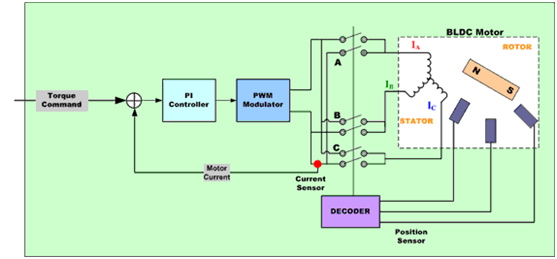
In this schematic, the current is to be controlled each time by a pair of motor terminals, while the third motor terminal is always electronically disconnected from the power supply.
Three Hall devices embedded in the larger motor are used to provide digital signals that measure the rotor position within a 60-degree sector and provide this information at the motor controller. Since the current flow is equal on two windings at a time and zero on the third, this method produces a current space vector with only one of six directions in common. As the motor is steered, the current at the motor terminals is switched electrically (rectified commutation) once for every 60 degrees of rotation, so the current space vector is always at the closest 30 degrees of the 90 degree phase shift.
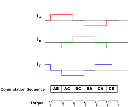
The current waveform in each winding is therefore trapezoidal, starting from zero to positive current to zero then to negative current.
This produces a current space vector that will approach equilibrium rotation as it steps up in 6 different directions with the rotation of the rotor.
In motor applications like air conditioning and frosting, the use of Hall sensors is not a constant option. Reverse potential sensors induced in unlinked windings can be used to achieve the same results.
Such trapezoidal drive systems are very common because of the simplicity of their control circuits, but they suffer from torque ripple problems during rectification.
Sinusoidal Rectified Commutation for BDLC Motors
Trapezoidal rectifier commutation is not sufficient to provide balanced and accurate brushless DC motor control. This is mainly due to the fact that the torque generated in a three-phase brushless motor (with a sinusoidal wave counter electromotive force) is defined by the following equation:
Rotating shaft torque = Kt [IRSin(o) + ISSin(o+120) +ITSin(o+240)]
Where:
o is the electrical angle of the rotating shaft
Kt is the torque constant of the motor
IR, IS and IT are the phase currents
If the phase currents are sinusoidal: IR = I0Sino; IS = I0Sin (+120o); IT = I0Sin (+240o)
will be obtained:
Shaft torque = 1.5I0*Kt (a constant independent of shaft angle)
A sinusoidally rectified commutated brushless motor controller endeavors to drive three motor windings whose three currents vary smoothly and sinusoidally as the motor rotates. The associated phases of these currents are selected such that they will produce smooth rotor current space vectors in directions orthogonal to the rotor with invariance. This eliminates the torque ripple and steering pulses associated with northerly steering.
In order to generate a smooth sinusoidal modulation of the motor current as the motor rotates, an accurate measurement of the rotor position is required. Hall devices only provide a rough calculation of the rotor position, which is not sufficient for this purpose. For this reason, angular feedback from an encoder or similar device is required.

Since the winding currents must be combined to produce a smooth constant rotor current space vector, and since each of the stator windings are positioned 120 degrees apart at an angle, the currents in each of the wire groups must be sinusoidal and phase shifted by 120 degrees. The position information from the encoder is used to synthesize two sine waves with a phase shift of 120 degrees between them. These signals are then multiplied by the torque command so that the amplitude of the sine wave is proportional to the required torque. As a result, the two sinusoidal current commands are appropriately phased, thus generating rotating stator current space vectors in the orthogonal direction.
The sinusoidal current command signal outputs a pair of P-I controllers that modulate the current in the two appropriate motor windings. The current in the third rotor winding is the negative sum of the controlled winding currents and therefore cannot be controlled separately. The output of each P-I controller is sent to a PWM modulator and then to the output bridge and the two motor terminals. The voltage applied to the third motor terminal is derived from the negative sum of the signals applied to the first two windings, appropriately used for three sinusoidal voltages spaced 120 degrees apart, respectively.
As a result, the actual output current waveform accurately tracks the sinusoidal current command signal, and the resulting current space vector rotates smoothly to be quantitatively stabilized and oriented in the desired direction.
The sinusoidal rectifier steering result of stabilized control cannot be achieved by trapezoidal rectifier steering in general. However, due to its high efficiency at low motor speeds, it will separate at high motor speeds. This is due to the fact that as the speed increases, the current return controllers must track a sinusoidal signal of increasing frequency. At the same time, they must overcome the counter electromotive force of the motor that increases in amplitude and frequency as the speed increases.
Since P-I controllers have finite gain and frequency response, time-invariant disturbances to the current control loop will cause phase lag and gain errors in the motor current that increase with higher speeds. This will interfere with the direction of the current space vector with respect to the rotor, thus causing a displacement with respect to the quadrature direction.
When this occurs, less torque can be produced by passing a certain amount of current, so more current is required to maintain torque. Efficiency decreases.
This decrease will continue as speed increases. At some point, the phase displacement of the current exceeds 90 degrees. When this occurs, the torque is reduced to zero. Through the combination of sinusoidal, the speed at this point above results in a negative torque and therefore is not realized.
AC Motor Algorithm
Scalar Control
Scalar control (or V/Hz control) is a simple method of controlling the speed of a command motor
The steady state model of the command motor is mainly used to obtain the technology, so transient performance is not possible. The system does not have a current loop. To control the motor, the three-phase power supply varies only in amplitude and frequency.
Vector control or magnetic field directional control
The torque in an electric motor varies as a function of the stator and rotor magnetic fields and peaks when the two fields are orthogonal to each other. In scalar-based control, the angle between the two magnetic fields changes significantly.
Vector control manages to create orthogonality again in AC motors. In order to control the torque, each generates a current from the generated magnetic flux to achieve the responsiveness of a DC machine.
Vector control of an AC commanded motor is similar to the control of a separately excited DC motor. In a DC motor, the magnetic field energy Φ F generated by the excitation current IF is orthogonal to the armature flux ΦA generated by the armature current IA. These magnetic fields are decoupled and stabilized with respect to each other. As a result, when the armature current is controlled to control torque, the magnetic field energy remains unaffected and a faster transient response is realized.
Field Oriented Control (FOC) of a three-phase AC motor consists of mimicking the operation of a DC motor. All controlled variables are mathematically transformed to DC instead of AC. its target independent control torque and flux.
There are two methods of magnetic field orientation control (FOC):
Direct FOC: The direction of the rotor flux angle is calculated directly from the flux observer.
Indirect FOC: The direction of the rotor flux angle is obtained indirectly by estimating or measuring the rotor speed and slip.
Vector control requires knowledge of the position of the rotor flux and can be calculated by advanced algorithms using knowledge of the terminal currents and voltages (using a dynamic model of an AC induction motor). However, from an implementation point of view, the need for computational resources is crucial.
Different approaches can be used to implement vector control algorithms. Feedforward techniques, model estimation and adaptive control techniques can all be used to enhance response and stability.
Vector control of AC motors: a deeper understanding
At the heart of a vector control algorithm are two important transformations: the Clark transformation, the Park transformation and their inverse. The use of Clark and Park transitions allows control of the rotor current into the rotor area. This allows a rotor control system to determine the voltage that should be supplied to the rotor in order to maximize the torque under dynamically changing loads.
CLARK TRANSFORMATION: The Clark mathematical transformation modifies a three-phase system into two coordinate systems:
Where Ia and Ib are components of the orthogonal reference plane and Io is the unimportant homoplanar component
Park transformation: the Park mathematical transformation converts the bi-directional static system into a rotating system vector
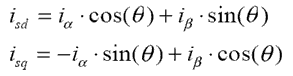
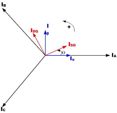
The two-phase α, β frame representation is computed by Clarke conversion and then fed into the vector rotation module where it rotates the angle θ to conform to the d, q frames attached to the rotor energy. The conversion of angle θ is realized according to the above equation.
Basic structure of magnetic field oriented vector control of AC motor
The Clarke transform uses the three-phase currents IA, IB, and IC to compute the two-phase orthogonal stator-axis currents Isd and Isq. These two currents in the fixed-coordinate stator phases are transformed into Isd and Isq, which become elements in the Park transform d, q. This is done by using the motor flux model to compute the rotor energy in the d, q frames. The currents Isd, Isq and the instantaneous flux angle θ calculated from the motor flux model are used to calculate the electric torque of the AC induction motor.
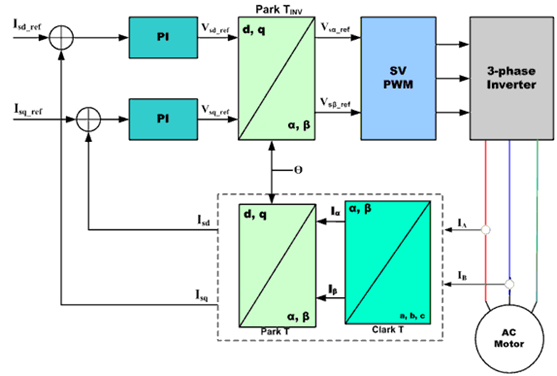
These derived values are compared with the reference values and updated by the PI controller.

An inherent advantage of vector-based motor control is that the same principle can be used to select the appropriate mathematical model to control each type of AC, PM-AC or BLDC motor separately.
Vector control of BLDC motors
BLDC motors are the main choice for field oriented vector control. Brushless motors with FOC can achieve higher efficiencies, up to 95%, and are also very efficient at high motor speeds.
Stepper motor control algorithm
The following is a schematic diagram of stepper motor control.
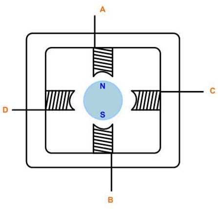
Stepper motor control usually uses bi-directional drive current, and its motor stepping is realized by switching the windings in sequence. Usually such stepper motors have 3 drive sequences:
1. Single-phase full-step drive:
In this mode, its windings are energized in the following sequence, AB/CD/BA/DC (BA indicates that the energization of winding AB is done in the reverse direction). This sequence is known as single-phase all-stepping mode, or wave drive mode. At any one time, only one phase is energized.
2. 2-phase full-step drive:
In this mode, both phases are energized together, so that the rotor is always between two poles. This mode is known as two-phase full-stepping, and this mode is the normal driving sequence for two-pole motors, which can output the maximum torque.
3. Half stepping mode:
This mode combines single-phase stepping and two-phase stepping in one power-up: single-phase power-up, then two-phase power-up, then single-phase power-up…, so the motor runs in half-step increments. This mode, known as half-step mode, halves the effective step angle of each excitation of the motor and its output torque is lower.
All of the above 3 modes can be used to rotate in the opposite direction (counterclockwise), but not if the order is reversed.
Usually, stepper motors have multiple poles in order to reduce the step angle, however, the number of windings and the driving order remain the same.
General purpose DC control algorithms
Speed control of general-purpose motors, especially those using 2 types of circuits:
1, Phase angle control
2、PWM chopper control
Phase angle control
Phase angle control is the simplest method of general-purpose motor speed control. Through the TRIAC point arc angle change to control the speed. Phase angle control is a very economical solution, however, the efficiency is not very high, easy electromagnetic interference (EMI).
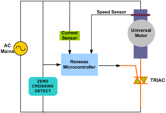
The above schematic shows the mechanism of phase angle control, a typical application of TRIAC speed control.The circumferential phase shift of the TRIAC gate pulses produces efficient voltages, resulting in different motor speeds, and an over-zero crossover detection circuit is used to establish a timing reference to delay the gate pulses.
PWM Chopper Control
PWM control is a more advanced solution for general purpose motor speed control. In this solution, the power MOFSET, or IGBT, turns on the high-frequency rectified AC line voltage, which in turn generates a time-varying voltage for the motor.
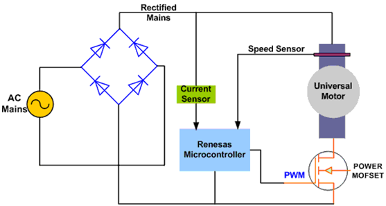
The switching frequency range is typically 10-20 KHz to eliminate noise. This method of control for general-purpose motors results in better current control and better EMI performance and, therefore, higher e
")


")